
Mapping Loads From CFD to FEA in Simcenter
Blog Article | March 27, 2026
Summary
Mapping Computational Fluid Dynamics (CFD) loads to Finite Element Analysis (FEA) enables engineers to translate real fluid-driven pressures and thermal effects into accurate structural responses, improving simulation fidelity and design confidence. Using Simcenter, this workflow helps reduce iterations, capture realistic loading conditions, and accelerate product development.
Key Topics Covered
-
CFD and FEA roles in multiphysics engineering workflows
-
Importance of mapping real fluid loads to structural models
-
Overview of Simcenter STAR-CCM+ and Simcenter 3D integration
-
End-to-end CFD-to-FEA load mapping process steps
-
Exporting and handling CFD pressure and temperature data
-
Field-based vs. mapped solution load transfer methods
-
Interpolation techniques used in load mapping
-
Mesh alignment considerations for accurate data transfer
-
Avoiding loss of peak loads during mapping
-
Validating simulation results with physical test data
-
Optional automation of CFD–FEA workflows
-
Common challenges including mesh mismatch and large datasets
Introduction
Modern engineering problems rarely exist within a single physical domain. Products are subjected to aerodynamic forces, thermal gradients, and fluid-induced pressures that directly impact structural performance. Treating these effects independently can lead to inaccurate assumptions and over-simplified models.
This is where CFD–FEA integration becomes essential.
Fluid–structure interaction (FSI) allows engineers to capture how fluid behavior—such as airflow pressure or convective heating—affects structural components. While fully coupled simulations are sometimes necessary, a more common and efficient approach is mapping CFD-derived loads into a structural FEA model.
This workflow enables teams to:
- Reduce design iterations by improving early-stage accuracy
- Capture realistic loading conditions instead of approximations
- Accelerate time-to-market through better-informed decisions
Within the Simcenter ecosystem, this process is both accessible and scalable, making it practical for a wide range of applications—from automotive cooling to aerospace structures.
Understanding CFD & FEA in Context
What Is CFD?
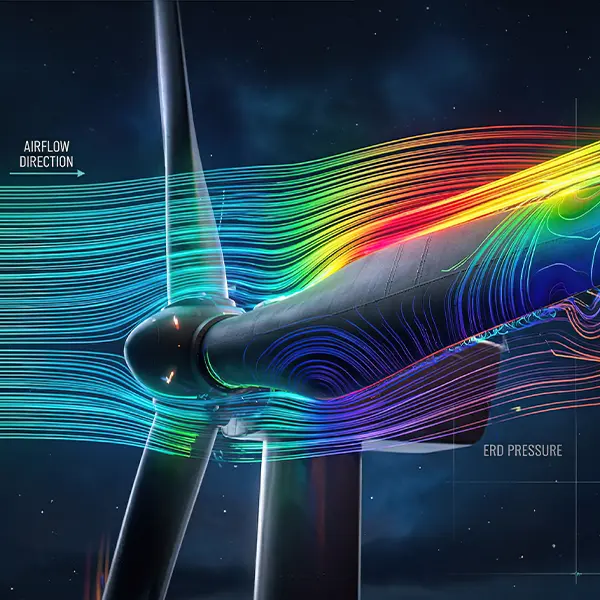
Computational Fluid Dynamics (CFD) is used to simulate how fluids—liquids and gases—behave under various conditions.
It Provides Detailed Insight Into:
- Pressure distributions
- Flow velocity and direction
- Turbulence and vortices
- Heat transfer and thermal gradients
Typical Applications Include:
- Aerodynamic analysis of vehicles or aircraft
- Thermal management in electronics
- Cooling system optimization
- Internal flow in piping or machinery
CFD results are inherently spatial and often highly non-uniform, which is why they are valuable—but also challenging—to transfer into structural models.
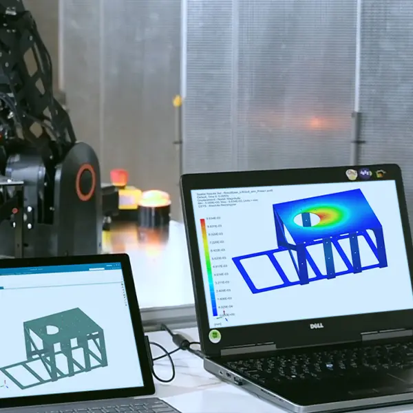
What Is FEA?
Finite Element Analysis (FEA) focuses on predicting how structures respond to loads.
It Evaluates:
- Stress and strain
- Deformation and displacement
- Structural stability
Fea Is Widely Used To Ensure That Components Meet:
- Strength requirements
- Safety factors
- Regulatory compliance
However, the accuracy of an FEA model is only as good as the loads applied to it. This is where CFD-derived data becomes critical.
Why Map CFD Loads to FEA?
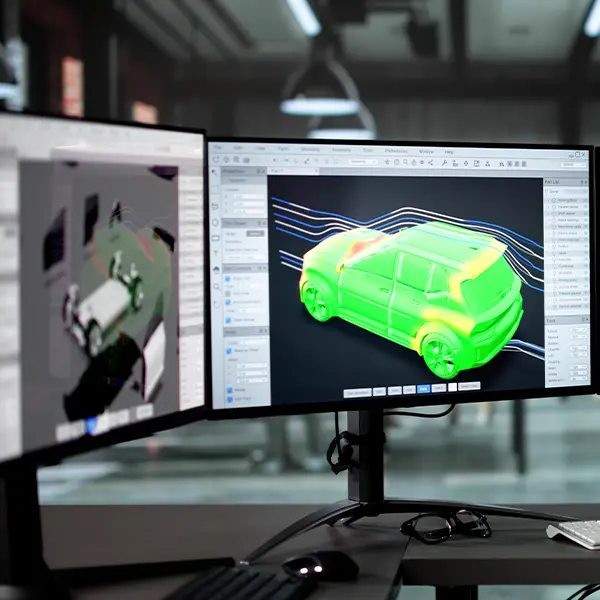
In many real-world scenarios, structural loads are driven by fluid behavior—not simple static assumptions.
For Example:
- Aerodynamic pressure on a wing varies across its surface
- Cooling airflow creates localized thermal gradients
- Internal flow induces uneven pressure distributions
Using Simplified Loads (e.g., uniform pressure) Can Lead to:
- Underprediction of stress in critical areas
- Overdesign due to conservative assumptions
- Missed failure modes
By Mapping Actual CFD Pressure & Temperature Fields, Engineers Can:
- Improve structural realism
- Capture localized effects
- Make more confident design decisions
Overview of Simcenter’s Multiphysics Capabilities
Integrated CAE Portfolio
The Simcenter portfolio provides a broad range of simulation tools across multiple physics domains.
Key Components Include:
-
Simcenter STAR-CCM+ for CFD
- Simcenter 3D for structural, thermal, and multiphysics FEA
- Additional capabilities for durability, electromagnetics, and system simulation
It’s important to note that STAR-CCM+ and Simcenter 3D are separate installations, but they are designed to work together efficiently.
This Ecosystem Enables:
- Geometry consistency across tools
- Structured data transfer workflows
- Built-in load mapping capabilities
Benefits of Using a Single Ecosystem
Working Within a Unified Simulation Environment Provides Several Practical Advantages:
1
Reduced Reliance on Neutral Formats
While formats like STEP can be used, native workflows reduce translation errors and preparation time.
2
Faster Data Transfer Between Domains
CFD results can be more directly leveraged in structural simulations without extensive reprocessing.
3
Improved Traceability
When integrated with PLM systems, teams can maintain clear relationships between:
- CAD geometry
- CFD simulations
- FEA results
This traceability becomes increasingly important in regulated industries or large-scale engineering programs.
CFD-to-FEA Load Mapping Helps Teams Make Better Decisions Earlier In The Development Process.
Explore how integrated Simcenter solutions can streamline your multiphysics workflows and improve confidence in your results.
Step-By-Step: How To Map CFD Loads to FEA in Simcenter
Step 1
Complete the CFD Simulation
Begin by running your CFD analysis in Simcenter STAR-CCM+.
Ensure the simulation is robust and reliable:
- Apply accurate boundary conditions
- Confirm mesh independence (mesh convergence)
- Validate turbulence models where applicable
Also determine the type of results needed:
- Steady-state / time-averaged for general structural loading
- Transient results if the structure is sensitive to time-dependent effects
Poor CFD quality will directly impact structural accuracy, so this step is critical.
Step 2
Export CFD Load Data
Once the CFD solution is complete, export the relevant files:
- Pressure distributions
- Temperature fields
Common formats include:
For fields:
- .csv
- .txt
For a mapped solution:
- .bun and .scd5 for results
- .map and .xml for mapping
The goal is to preserve:
- Spatial resolution
- Field accuracy
- Association with geometry or mesh
Step 3
Set up the Structural Model in Simcenter 3D
In Simcenter 3D, prepare your structural model:
- Import or associate the same geometry used in CFD
- Define material properties
- Apply boundary conditions (constraints, supports, etc.)
- Generate an appropriate structural mesh
Step 4
Map CFD Results to Structural Mesh
This is the core step: transferring CFD data onto the FEA model.
There are two main ways to go about this:
Table Fields
- Used when CFD results are exported as data in a .csv or .txt format
- The field is then added to a pressure or temperature load
- Simcenter 3D interpolates the values onto the structural mesh
Interpolation Methods
- Weighted Least Squares
- Inverse Distance Weighting
- Approximate Nearest Neighbor
You can also view the contours of the load once mapped to make sure it interpolated correctly.
Mapped Solution
- Used when importing results directly from another solution
- Create a new mapped solution
- Define the source model results file (.bun or .scd5)
- Define the source model mapping file (.map or .xml
Step 5
Run the FEA Analysis
With mapped loads applied, run the structural simulation.
Typical outputs include:
- Stress (e.g., von Mises stress)
- Strain
- Displacement
Post-processing involves:
- Identifying high-stress regions
- Comparing results to allowable limits
- Evaluating safety factors or compliance criteria
At this stage, engineers can iterate on the design if needed.
Tips & Best Practices
Accurate CFD-to-FEA load mapping depends on maintaining good mesh alignment in critical regions, selecting mapping methods that preserve peak loads, and validating simulation results against physical test data. While automation can streamline repeated workflows, the priority should remain on ensuring load accuracy and physical realism to avoid misleading structural results.
Mesh Compatibility
While CFD and FEA meshes differ, alignment still matters.
Best Practices:
- Maintain reasonable geometric consistency between models
- Use finer meshes in regions with high load gradients: leading edges, interfaces, sharp curvature
This improves mapping accuracy and reduces interpolation errors.
Avoid Underestimating Structural Loads
When selecting mapping methods, it’s important to avoid smoothing out peak loads excessively.
Some Interpolation Approaches Can:
- Reduce local pressure peaks
- Underestimate stress concentrations
In Critical Applications, Consider Approaches That:
- Preserve load magnitude
- Capture localized extremes
The goal is not to always use one method, but to ensure that structural risk is not unintentionally minimized.
Validate With Physical Test Data
Simulation Should Be Grounded in Reality
Whenever Possible:
- Compare CFD predictions with wind tunnel or lab data
- Validate pressure distributions or thermal profiles
This ensures that mapped loads reflect real-world conditions.
Automate With Simcenter Workflows (Optional)
For teams running repeated analyses, automation can help.
Options Include:
- Scripting workflows with NX Open
- Creating reusable templates
- Standardizing CFD-to-FEA pipelines
This Is Especially Useful In:
- Design optimization loops
- Parametric studies
However, for many use cases, manual workflows are already efficient and sufficient.
Real-World Applications
CFD-to-FEA load mapping is widely used across industries to translate fluid and thermal effects into structural insights, from underhood thermal loading in automotive to aerodynamic pressure on aerospace structures and thermal deformation in electronics. This approach enables engineers to evaluate real operating conditions and improve product reliability across diverse applications.
Automotive
CFD-to-FEA Mapping Is Commonly Used To Evaluate:
- Underhood airflow effects
- Thermal loading on components
This Helps Assess:
- Thermal fatigue
- Material durability under heat exposure
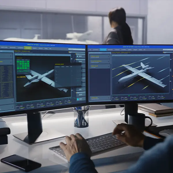
Aerospace
In Aerospace Applications:
- Aerodynamic pressures are mapped onto wings, fuselage, or control surfaces
This Helps Assess:
- Structural validation under realistic flight conditions
- Identification of high-stress regions
Electronics
For Electronics:
- CFD models simulate cooling airflow
- Thermal results are mapped to structural models
This Helps Predict:
- PCB deformation
- Thermal-induced stress on components
Common Challenges & How To Solve Them
Common challenges in CFD-to-FEA load mapping include mismatched geometries, large data sets, and handling transient results, all of which can impact accuracy and performance if not addressed properly. These issues can be mitigated through geometry alignment, efficient data reduction strategies, and appropriate use of time-dependent load cases to ensure reliable structural predictions.
Mismatched Geometries or Meshes
Differences between CFD and FEA models can create mapping issues.
Solutions:
- Use geometry associativity tools in Simcenter
- Repair gaps or inconsistencies
- Align boundaries before mapping
Large File Sizes
CFD datasets can be very large.
To Manage This:
- Use surface-based mapping instead of full volume data
- Reduce unnecessary field outputs
This improves performance without sacrificing key information.
Time-Dependent Loads
Transient CFD results introduce additional complexity.
Approaches Include:
- Mapping loads across multiple time steps
- Using dynamic or transient FEA solvers
- Defining multi-step load cases
This Is Especially Important For:
- Vibrations
- Pulsating flows
- Cyclic loading
Conclusion
Mapping loads from CFD to FEA is a practical and powerful approach to improving simulation accuracy.
By transferring realistic pressure and thermal fields into structural models, engineers can:
- Better predict product performance
- Reduce reliance on assumptions
- Identify risks earlier in the design process
The Simcenter ecosystem provides the tools needed to make this workflow efficient and repeatable, even across complex multiphysics problems.
Investing in CFD–FEA integration ultimately leads to:
- Faster design iterations
- Improved product reliability
Lower development costs
Key Takeaways
- CFD provides realistic pressure and thermal loads that improve FEA accuracy
- Load mapping bridges fluid and structural simulations without full FSI coupling
- Simcenter supports this workflow through STAR-CCM+ and Simcenter 3D
- Interpolation and area-based methods enable accurate data transfer between meshes
- Validation and careful method selection are critical to avoid underestimating loads
- The workflow applies across automotive, aerospace, and electronics industries
