

Old vs. New Siemens NX Sketch Solver: What Changed in Modern Sketching
Blog Article | July 10, 2026
Summary
This blog explains the key differences between the old and new Siemens NX Sketch Solver workflows, with a focus on how NX sketching has evolved from manual constraint management to a more automated, solver-driven approach. It covers traditional constraint-driven sketching, modern sketch solver behavior, inferred relationships, Persistent Relations, fully constrained sketches, under-defined and over-defined sketch conditions, and best practices for building cleaner, more flexible parametric models. The article is designed for intermediate and expert NX users who want to understand how the newer Sketch Solver changes sketch creation, editing behavior, constraint strategy, and design intent in Siemens NX.
Key Topics Covered
Introduction
Sketches are often the foundation of a parametric CAD model. They define profiles for extrudes, revolves, cuts, patterns, ribs, slots, bosses, and many other downstream features. When a sketch is built well, the model updates predictably. When it is under-defined, over-defined, or constrained without clear intent, downstream edits can become difficult to control.
In Siemens NX, this topic has become especially important because sketching has changed significantly over time. Historically, NX users relied on a traditional constraint-driven sketching workflow where geometric relationships were created, displayed, and managed explicitly. With the introduction of the modern Sketch Solver in NX 1926, released in June 2020, Siemens moved toward a more automated solving approach that places less emphasis on manually managing every constraint.
For intermediate and expert NX users, understanding this shift is important. The newer workflow can feel unfamiliar at first, especially for users trained to fully define every relationship manually. However, when used correctly, the modern Sketch Solver can help reduce sketch clutter, improve edit behavior, and keep the focus on design intent instead of constraint bookkeeping.
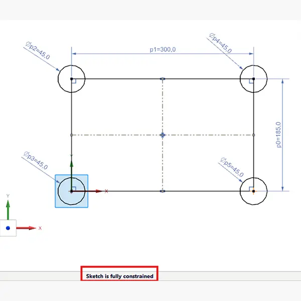
Traditional Constraint-Driven Sketching in NX
In a traditional NX sketching workflow, users manually create and manage geometric constraints and dimensions to control sketch geometry. Relationships such as horizontal, vertical, tangent, parallel, perpendicular, coincident, concentric, equal, and symmetric constraints are explicitly applied to define how sketch entities behave.
This method gives engineers a high degree of control. Users can inspect individual constraints, understand exactly why a line is horizontal or why an arc remains tangent to another curve, and deliberately build relationships into the sketch. For experienced NX users, or engineers coming from other parametric CAD systems, this approach is familiar because each relationship is visible and directly managed.
This level of control is valuable when design intent is complex. For example, a mounting slot may need to stay centered on a datum while its length changes. A hole pattern may need to remain symmetric about a centerline. A bracket profile may need tangent transitions that preserve manufacturability or stress continuity. In these cases, constraints and dimensions are not just sketch mechanics; they are the engineering logic behind the model.
The challenge is that traditional constraint-driven sketching can become time-consuming. Large sketches may require many manually applied relations. Over time, sketches can also accumulate more dimensions and constraints than necessary. This makes them harder to troubleshoot and more fragile during edits.
A sketch with redundant or conflicting relationships may technically appear controlled, but it may not be flexible. The user may spend more time diagnosing why a profile will not move, why a dimension creates an error, or why a downstream feature fails than actually refining the design.
What Changed With the Modern NX Sketch Solver
The modern NX Sketch Solver introduced in NX 1926 represents a different way of thinking about sketch control. Instead of requiring users to manually create and maintain large numbers of sketch relations, the solver automatically identifies geometric relationships and presents them when needed.
This shifts the sketching workflow away from manual constraint management and toward geometry creation, refinement, and design intent. Rather than defining every relationship up front, users can focus on creating the shape they need while NX evaluates the geometric conditions required to maintain predictable behavior.
One of the primary goals of the new solver is to reduce the effort associated with geometric constraint creation. In a traditional workflow, a meaningful portion of sketching time can be spent adding and managing relations. The solver-driven approach reduces that burden by automatically detecting appropriate relationships and helping maintain the sketch with fewer unnecessary constraints.
This does not mean constraints no longer matter. It means the system is taking on more of the responsibility for identifying and solving geometric relationships. For the user, the practical benefit is a cleaner sketching experience with less visual and structural clutter.
In modern NX sketching, the solver works to identify only the constraints needed to maintain the intended behavior of the geometry. This can reduce the tendency to over-build sketches with redundant relationships. Combined with enhancements such as improved drag behavior, associative sketch patterning, and localized solving for complex sketches, the modern workflow is designed to make sketching faster, more intuitive, and easier to maintain.
From Constraint Count to Design Intent
For experienced users, one of the biggest mindset shifts is moving away from the idea that a good sketch is defined by how many constraints are visible. A good sketch is not the one with the most constraints. It is the one that behaves correctly when edited.
In a traditional workflow, users often think in terms of “What constraints do I need to add?” In the modern NX workflow, a better question is “What behavior does this sketch need to preserve?”
For example:
- Should this hole stay centered on the part?
- Should these two features remain symmetric?
- Should this profile grow equally in both directions?
- Should this arc remain tangent during dimensional changes?
- Should this imported curve be locked, referenced, or rebuilt parametrically?
These questions focus on design intent. The solver can assist with geometric relationships, but the engineer still decides which relationships matter.
This is where the modern solver and traditional constraint discipline overlap. The new solver reduces the manual burden, but it does not replace sound modeling judgment.
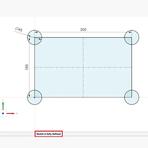
What Fully Constrained Means in a Solver-Driven NX Workflow
A fully constrained sketch is one where the size, shape, position, and relationships of the sketch geometry are completely defined. In practical terms, nothing should move, rotate, resize, or change shape unless the user intentionally edits a dimension or relationship. This remains a useful modeling goal, especially for production parts, released designs, manufacturing features, mating interfaces, and geometry tied to downstream operations.
However, in modern NX, full constraint should be understood in terms of behavior rather than constraint volume. The goal is not to manually lock down every entity with as many relations as possible. The goal is to define the sketch clearly enough that it updates predictably while preserving the intended engineering logic.
A sketch is typically controlled by two categories of information:
- Dimensional control: length, radius, diameter, angle, offset, spacing, and position
- Geometric control: coincident, tangent, parallel, perpendicular, concentric, symmetric, equal, horizontal, and vertical relationships
The best sketches use both. Dimensions define measurable requirements. Geometric relationships define how entities should stay connected, aligned, centered, or smooth as the design changes.
For example, two holes that must remain the same size should usually use one diameter dimension and an equal relationship rather than two independent diameter dimensions. A slot that must remain centered should use symmetry or midpoint logic rather than unrelated offset dimensions that can drift apart during edits.
Persistent Relations & Inferred Geometry in NX
One practical NX setting to understand is Create Persistent Relations. When enabled, NX can retain inferred sketch relationships as persistent constraints while geometry is created. For example, if NX infers that a line is horizontal, that two endpoints are coincident, or that a curve is tangent to another entity, persistent relations can help preserve those relationships as actual sketch constraints.
This setting is important because it bridges traditional and modern sketch behavior. Automatic inferencing helps users sketch quickly. Persistent relations help ensure that important inferred relationships remain part of the sketch definition.
For many parametric workflows, keeping Create Persistent Relations enabled is useful because it reduces the amount of manual cleanup required later. However, users should still review sketch behavior. Automatically retained relationships are helpful when they match design intent, but they can become a problem if the inferred relationship was accidental.
For example, if a line was drawn nearly horizontal and NX inferred a horizontal relationship, that may be correct. But if the design later requires that line to be angled, the retained relationship may need to be removed or replaced with a more appropriate dimension.
The practical rule is simple: let NX help, but do not stop thinking like the model owner.
Under-Defined, Fully-Defined, & Over-Defined Sketches
Even with the modern solver, it is still useful to understand the three common sketch states: under-defined, fully defined, and over-defined.
- An under-defined sketch does not have enough information to control all geometry. Some entities can still move, rotate, resize, or change shape unexpectedly. Common causes include missing dimensions, floating endpoints, unconstrained circle centers, arcs without tangent relationships, or geometry not tied to a reliable reference.
- A fully defined sketch has enough information to control the sketch’s size, position, and relationships. The geometry updates predictably when a driving dimension changes.
-
An over-defined sketch contains redundant, conflicting, or excessive relationships. This can happen when multiple dimensions control the same distance, a fixed constraint conflicts with a location dimension, or a geometric constraint conflicts with an angular dimension.
The modern NX solver can help reduce unnecessary constraints, but it does not eliminate the possibility of poor sketch definition. Engineers still need to evaluate whether a sketch is constrained in a way that supports future edits.
Practical Best Practices for Sketching in Modern NX
A solver-driven workflow does not mean sketching becomes automatic. It means engineers can use the solver to reduce repetitive constraint work while still applying deliberate control where it matters.
1
Anchor the Sketch Early
A sketch should usually be related to a reliable reference such as the origin, datum geometry, projected geometry, or a meaningful construction reference. A profile with correct size dimensions can still be under-defined if its position is floating.
For example, a circle with a diameter dimension is not fully controlled if its center can move. Locate the center relative to the origin, an axis, a datum, or another feature reference.
2
Use Dimensions for Engineering Requirements
Use dimensions where values matter: hole diameter, slot width, wall thickness, center-to-center spacing, offset distance, radius, and angle.
Avoid replacing meaningful dimensions with fixed geometry. A fix constraint may stop geometry from moving, but it may not communicate why the geometry belongs there.
3
Use Geometric Relationships for Design Logic
Geometric relationships are best used when the relationship matters more than the numerical value. Tangency, symmetry, concentricity, parallelism, and equality often communicate intent more clearly than extra dimensions.
For example, if two circles should always share the same center, use concentric logic. If two sides of a profile should remain equal, use an equal relationship rather than duplicating dimensions.
4
Avoid Redundant Constraints
More constraints do not always create a better sketch. Redundant constraints can make edits harder and increase the chance of over-defined conditions.
A clean sketch uses the minimum number of dimensions and relationships needed to preserve design intent. This is especially important in larger sketches, where unnecessary relationships can make troubleshooting more difficult.
5
Be Careful With Fix Constraints
Fix constraints can be useful for imported geometry, reference layouts, or temporary control, but they should be used carefully. In production modeling, dimensions and geometric relationships usually communicate design intent more clearly.
A fixed line may be stable, but another engineer may not know whether it represents a datum, a manufacturing requirement, or simply a locked piece of geometry.
6
Test the Sketch by Editing It
A sketch is not proven just because it appears fully constrained. Change a key dimension and observe the update. Drag geometry where appropriate. Check whether the sketch behaves as intended.
This is especially useful when transitioning from older sketching habits to the modern NX solver. The goal is not just a constrained sketch; the goal is a sketch that edits cleanly.
Maximize Productivity with Customized NX Training
Equip your engineering team with the skills to fully leverage NX Sketch. Saratech tailors training to your workflows, helping users adapt faster, improve modeling consistency, reduce design errors, and accelerate product development across your organization.
When Full Constraint Is Less Critical
Although fully constraining sketches is a strong best practice, it is not always mandatory. During early concept modeling, layout exploration, industrial design studies, or temporary construction work, speed and flexibility may matter more than full definition.
However, for production models, manufacturing features, interfaces, released geometry, simulation-driven geometry, CAM-driven geometry, and anything used downstream, fully defining the sketch remains strongly recommended.
In other words, the required level of sketch control should match the model’s purpose. Exploratory geometry can be flexible. Released engineering geometry should be reliable.
Why This Matters for NX Users
The modern NX Sketch Solver reflects Siemens’ preferred direction for sketch creation: faster geometry development, less manual constraint overhead, and cleaner sketch behavior. For experienced users, the transition may initially feel like a loss of direct control because not every relationship is managed the same way it was in older workflows.
In practice, the control is still there, but the workflow is different. NX is handling more of the solving process, while the engineer remains responsible for defining meaningful design intent.
The strongest NX users will not simply rely on automation or manually constrain everything out of habit. They will combine both approaches: use the solver to reduce repetitive work, then apply dimensions and relationships deliberately where the design requires them.
Conclusion
Understanding the modern NX Sketch Solver is not just about learning a new sketching tool. It is about adapting to a different modeling philosophy. Instead of manually managing every relationship, users can allow NX to identify and solve many geometric conditions while they focus on the engineering behavior the sketch needs to preserve.
For intermediate and expert users, the opportunity is to sketch faster without giving up control. By anchoring geometry intentionally, using dimensions for engineering requirements, applying relationships where they communicate design logic, and avoiding redundant constraints, teams can build NX sketches that are both efficient and robust.
If your team is updating NX modeling standards, training users on newer releases, or trying to improve parametric model quality, sketching practices are a practical place to start. Strong sketch intent leads to stronger models, cleaner edits, and more reliable downstream engineering workflows.
Key Takeaways
- NX sketching has shifted from a heavily manual, constraint-driven workflow toward a more automated solver-driven workflow.
- The modern Sketch Solver, introduced in NX 1926, helps reduce manual constraint creation and supports cleaner sketch behavior.
- Fully constrained sketches still matter, especially for production CAD models and downstream design stability.
- The goal is not to add the most constraints; the goal is to capture design intent with the fewest necessary dimensions and relationships.
- Create Persistent Relations can help retain inferred sketch relationships, but users should still review whether those relationships match the design intent.
- Under-defined sketches can move unexpectedly, while over-defined sketches can become difficult to edit and troubleshoot.
- Modern NX sketching works best when engineers combine solver assistance with disciplined parametric modeling practices.
