
What is Third Angle Projection? Purpose, Views & Applications
Blog Article | October 16, 2025
Summary
Third Angle Projection (TAP) is the standard orthographic drawing method in North America for representing 3D objects in 2D views. It provides clear, standardized front, top, and side views, paired with isometric views when needed, to eliminate ambiguity, reduce errors, and ensure accurate communication of design intent. TAP is widely applied across manufacturing, aerospace, automotive, architecture, and product design. Drawings include a TAP symbol to confirm projection method, ensuring consistency across teams and global manufacturing.
Key Topics Covered
-
Definition of Third Angle Projection (TAP)
-
Purpose: clear communication, reduce errors, standardization
-
Industries: manufacturing, aerospace, automotive, architecture, product design
-
Orthographic views: front, top (plan), side
-
Isometric 3D view paired with TAP
-
TAP layout: top above front, right side to the right
-
Benefits: intuitive readability, reduced errors, U.S./Canada standard
-
Flat pattern for sheet metal considerations
-
TAP symbol: truncated cone for clarity
What is Third Angle Projection?
In engineering and manufacturing, precision is everything. Communicating the exact dimensions, geometry, and relationships of a part requires a standardized method of drawing. Third Angle Projection (TAP) is the most widely used type of view layout for engineering drawings in the United States by a long shot. It is a standardized system of orthographic projection that allows engineers and designers to represent a three-dimensional object in two dimensions, showing multiple views of the same component in a clear, consistent, and easy-to-read format.
Its primary purpose is to eliminate ambiguity in design communication, ensuring that manufacturers, engineers, and machinists can interpret drawings without error.
Industries Where TAP is Commonly Applied:


Basics of Orthographic & Isometric Projection
Before understanding Third Angle Projection, it helps to review the two fundamental approaches to technical drawings: orthographic projection and isometric projection.
Orthographic projection represents a 3D object using multiple 2D views, each projected onto a specific plane:
- Horizontal Plane (HP): Represents the top view (Plan View).
- Vertical Plane (VP): Represents the front view.
- Side or Profile Plane (PP): Represents the side view.
Each projection captures a specific angle of the object, providing the viewer with complete information. A helpful way to visualize TAP views is to imagine the part sitting in a bowl: move the part up to see the top, down for the bottom, left or right for side views.
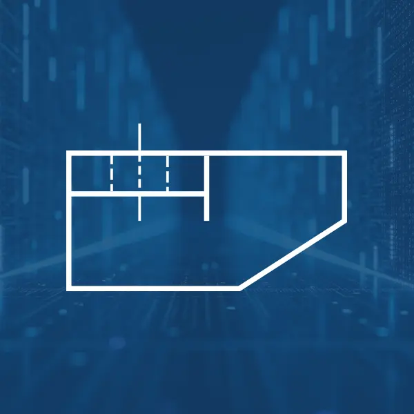
Shows the layout and dimensions of the object as if viewed from above.

Displays the height and width of the object as if viewed from the front.

Tip for sheet metal parts: These usually use a Flat Pattern, which unfolds the bent sheet metal into a flat layout for stamping, cutting, or machining. Showing a TAP side view for these parts is often unnecessary since only the material thickness and cut geometry are relevant.
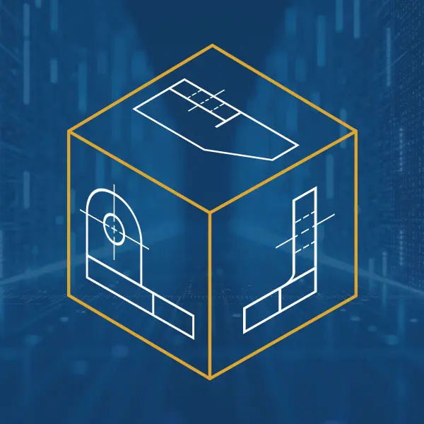
While orthographic projections break an object into multiple 2D views, an isometric view represents the object in 3D. It shows three sides at once, offering a more intuitive sense of shape.
In Third Angle Projection, orthographic views are usually paired with an isometric view to aid interpretation. The primary 2D views used are:
- Front View: The most descriptive side of the object.
- Side View: Usually the right-side view for clarity.
- Plan View (Top View): Shows features from above.
Together, these views provide both dimensional accuracy and an overall sense of the object’s form.
Third Angle Projection Characteristics
The defining characteristic of Third Angle Projection is how the views are arranged relative to one another. Unlike First Angle Projection (commonly used in Europe and Asia), Third Angle Projection follows this layout:
- Top View (Plan View): Placed above the Front View.
- Right Side View: Placed to the right of the Front View.
- Left Side View (if needed): Placed to the left.
This arrangement mirrors how we naturally perceive objects. If you look at the front of an object, the top view logically goes above it, and the right side view goes to the right.
Benefits of Third Angle Projection
Aligns with how people visualize objects in space.
Views are easier to interpret, especially for complex parts.
Widely adopted in the U.S. and Canada, making it the default for most engineering teams.

Streamline Your Engineering with Expert Support
Ensure your technical drawings and product data are accurate and production-ready. Saratech’s engineering services and Siemens software solutions help you go from concept to manufacturing with confidence.
Third Angle Projection Symbol
To avoid confusion between First and Third Angle Projection, engineering drawings include a projection symbol in the title block or near the drawing notes.
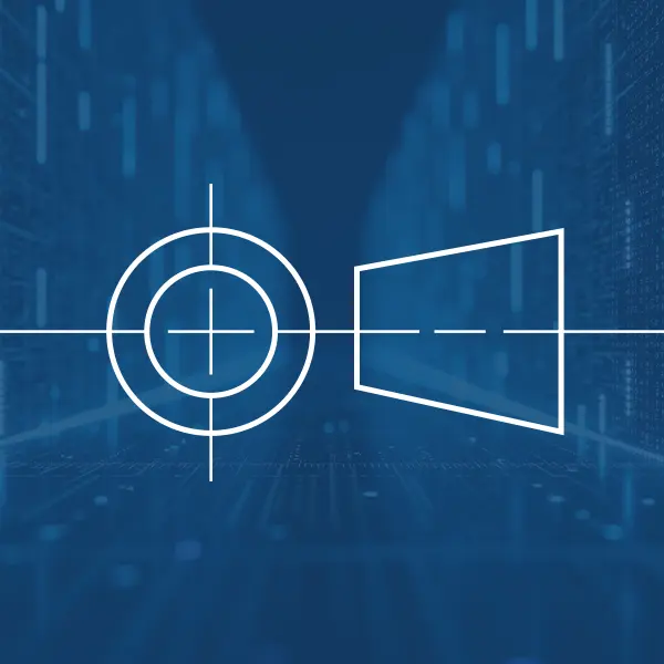
The Third Angle Projection symbol is a truncated cone shown in two views:
- Front view: A circle representing the base of the cone.
- Side view: Appears as a triangle with the small end on the left.
This simple icon confirms that the drawing uses Third Angle Projection, ensuring clarity for global teams and manufacturers.
Conclusion & Key Takeaways
Third Angle Projection is more than just a drawing convention—it is a critical tool for communicating precise engineering information. By breaking an object into standardized views, it eliminates ambiguity, reduces errors, and ensures consistency across design and manufacturing.
Key Takeaways:
- TAP is the standard projection method in North America.
- It provides clear, intuitive placement of views for easy interpretation.
- Essential in industries that demand accuracy, from aerospace to consumer products.
- The projection symbol on a drawing prevents misinterpretation across international teams.
For engineers, designers, and manufacturers, mastering Third Angle Projection is foundational to creating and interpreting technical drawings that drive innovation and production.
