

What Are Typical Notes to Include in an Engineering Drawing?
Blog Article | July 24, 2026
Summary
Engineering drawing notes clarify technical requirements that cannot be fully captured through geometry, dimensions, tolerances, symbols, CAD data, title block fields, or revision tables. They help communicate manufacturing expectations, material and process requirements, assembly conditions, local feature requirements, and unique verification conditions while supporting downstream documentation such as work instructions, inspection planning, supplier requirements, and maintenance records. Drawing notes should be numbered, concise, technically specific, and aligned with company, customer, industry, or program drafting standards. They should not duplicate controlled information such as block tolerances, title block data, revision history, approval information, or surface finish defaults, and they should not replace quality plans, inspection plans, manufacturing plans, or higher-level requirements.
Key Topics Covered
Engineering Drawing Notes: What to Include & Best Practices
Engineering drawings are part of the technical definition that translates product requirements into a controlled format for manufacturing, assembly, and verification. They communicate design intent through views, dimensions, tolerances, symbols, title block information, revision history, and notes.
However, an engineering drawing should not be treated as the sole technical or contractual requirement in every case. Drawing errors can exist, and drawings may be superseded by contractual language, regulatory requirements, customer specifications, or other higher-level documentation. In that context, drawing notes help clarify technical requirements that do not fit neatly into dimensions, views, symbols, CAD data, title block fields, or revision tables.
Well-written engineering drawing notes improve clarity for manufacturing, inspection planning, suppliers, assembly teams, and downstream documentation. Poorly written notes can create ambiguity, duplicate requirements, or conflict with information already controlled elsewhere on the drawing.
This guide explains common types of engineering drawing notes, where they typically belong, what should stay outside the notes list, and best practices for writing notes that are clear, numbered, and technically useful. This blog is based on the provided Saratech outline and SME refinements.
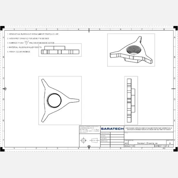
Why Engineering Drawing Notes Are Important
Engineering drawing notes are used to communicate technical information that cannot be clearly or efficiently captured through geometry, dimensions, tolerances, or standard symbols alone. For example, a drawing view may show the shape of a bracket, and the dimensions may define hole locations, bend radii, and edge distances, but the drawing may still need notes to communicate requirements such as material processing, masking before coating, part marking, assembly sequence, or special verification conditions.
Drawing Notes Help:
- Clarify manufacturing expectations.
- Communicate material, process, assembly, or other technical requirements.
- Connect requirements, CAD data, and production activity.
- Support downstream documentation such as work instructions, inspection planning, maintenance manuals, supplier requirements, and controlled manufacturing documentation.
The goal is not to add extra text for its own sake. The goal is to define requirements clearly enough that engineering intent can be carried through manufacturing, assembly, inspection, and documentation without unnecessary interpretation.
What Engineering Drawing Notes Should & Should Not Control
Drawing notes should clarify technical requirements. They should not replace quality plans, inspection plans, manufacturing plans, or higher-level requirements.
For example, a drawing note may define a unique verification condition, such as requiring a thin or flexible part to be measured in a restrained condition. That is a technical requirement because it defines the condition under which the part must conform.
However, the drawing generally should not prescribe the inspection tool or quality control method unless that method is explicitly part of the technical definition. The quality system, inspection plan, customer requirements, and applicable standards typically determine how inspection is performed.
A useful way to think about this is: Drawing notes define what must be true about the part or assembly and should not define the entire process for proving it.
Types of Engineering Notes
Engineering drawing notes generally fall into two broad types:
- General Notes
- Local Notes
General notes apply broadly to the drawing, part, or assembly, while local notes apply to a specific feature, surface, item, or area. Understanding the difference helps keep requirements organized, easy to reference, and clear for manufacturing, assembly, inspection planning, and downstream documentation.
Engineering General Notes
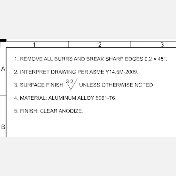
General notes apply to the entire drawing, part, or assembly unless otherwise specified. They are typically placed in a dedicated notes block or notes section.
General notes should always be numbered, not bulleted. Numbered notes are easier to reference in downstream artifacts such as work instructions, maintenance manuals, inspection documents, supplier requirements, nonconformance reports, and other controlled documentation.
Examples of General Notes May Include:
- REMOVE BURRS AND SHARP EDGES UNLESS OTHERWISE SPECIFIED.
- APPLY FINISH PER APPLICABLE SPECIFICATION.
- PROTECT SEALING SURFACES DURING PROCESSING.
- MARK PART NUMBER AND REVISION PER APPLICABLE SPECIFICATION.
The exact language should follow the controlling drawing standard. The examples above are generic and should not be copied into a production drawing unless they match the applicable company or customer requirements.
Where Engineering Notes Fit in the Drawing
General notes are typically placed in a dedicated notes section. In many company drawing templates, this section appears in the upper left quadrant of the sheet, but the exact location depends on the company, customer, or program standard.
This placement often keeps the drawing readable. Many drawing formats place the title block in the lower right, the bill of materials above the title block, and the revision block in the upper right. If the notes list were placed too close to those areas, the sheet could become crowded.
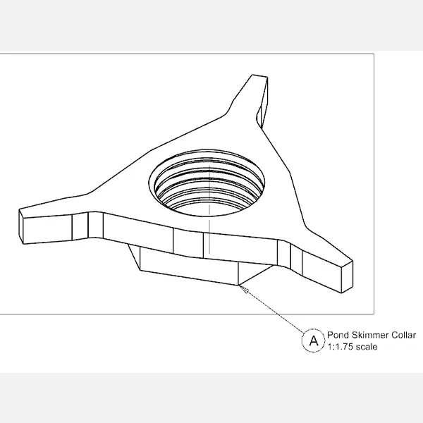
A local note applies to a specific feature, item, surface, or area of the drawing. These notes are usually placed near the applicable part or feature. They may use a leader line, but they do not always need one. The best placement is the one that makes the note’s application clear without cluttering the view.
Regardless of note location, drafting standards matter. Always follow the company, customer, organization, or program requirements for note placement, font, size, formatting, and other drawing conventions.
Engineering Local Notes
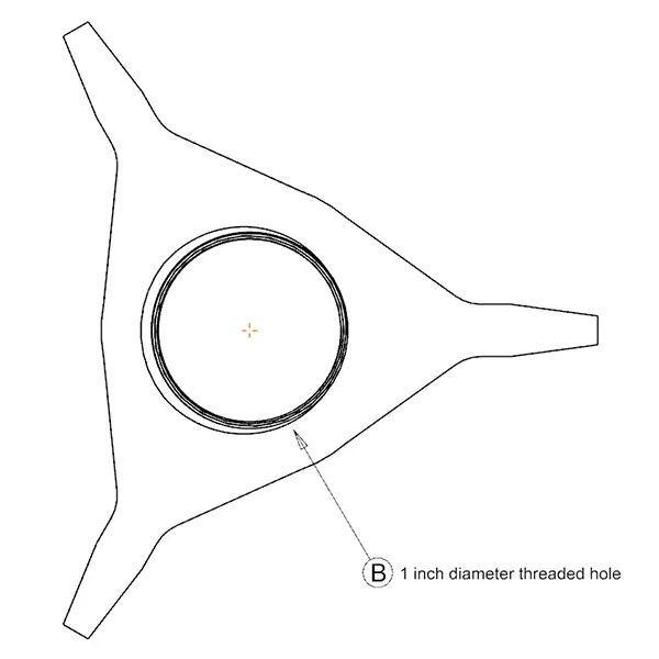
Local notes apply to a specific feature, item, surface, or area of the drawing. They are placed near the relevant geometry so the reader can quickly understand what the note controls.
A local note may identify a surface that must be masked before coating, a threaded feature that must remain free of finish, or a feature that must be measured in a specific condition. Some local notes use leader lines; others may be placed adjacent to the feature without a leader if the relationship is still clear.
Examples of Local Notes May Include:
- MASK THIS SURFACE PRIOR TO COATING.
- MEASURE FEATURE IN RESTRAINED CONDITION.
- DO NOT COAT THREADS.
- INSTALL INSERT FLUSH TO 0.005 BELOW SURFACE.
The key requirement is clarity. A local note should not leave the manufacturer, inspector, or assembler guessing which feature it applies to.
Common Categories of Engineering General Notes
General notes can cover several types of technical requirements, depending on the part, assembly, material, process, and applicable drawing standard. These categories help organize requirements that apply broadly across the drawing, such as material processing, manufacturing instructions, finishing, assembly, or inspection-related conditions. Grouping notes by category makes the drawing easier to read and reduces the risk of missing important requirements.
Engineering Expertise That Moves Projects Forward
Saratech is an engineering solutions partner that helps organizations solve design, manufacturing, simulation, automation, and product lifecycle challenges with expert engineering and proven methodologies. Get started with an expert today.
Engineered Features Built Directly Into the Tool
Material and process notes define requirements related to material selection, material condition, and required processing.
Material & Process Notes May Include Requirements For:
- Material specifications
- Heat treatment
- Plating
- Anodizing
- Passivation
- Cleaning
- Stress relief
- Welding
- Bonding
- Other required processing steps
For example, a part may need to be manufactured from a specific aluminum alloy, heat treated to a required condition, anodized after machining, and protected from contamination before assembly. Some of those requirements may be captured in material fields, specifications, or finish callouts. Others may require a clear drawing note.
These notes should be specific, but they should not attempt to rewrite the full process specification. If a company or customer specification already defines the process, the note should reference the applicable requirement in the correct format.
Manufacturing Instructions
Manufacturing notes communicate technical requirements relevant to fabrication or processing. They should not duplicate dimensions, tolerances, or symbols already shown elsewhere on the drawing unless the information is clearly identified as reference only and allowed by the applicable standard.
Manufacturing notes may address requirements such as burr removal, grain direction, masking, or areas that require special care during processing.
Examples May Include:
- REMOVE BURRS AND SHARP EDGES UNLESS OTHERWISE SPECIFIED.
- MAINTAIN GRAIN DIRECTION AS SHOWN.
- PROTECT SURFACES DURING PROCESSING.
- DO NOT BREAK THROUGH A SPECIFIED WALL.
A manufacturing note should communicate a requirement, not a preference. For example, “MAKE EDGES NICE” is not appropriate drawing language. A better note would define the required edge condition, reference a standard, or use an approved company note.
Finishing & Coating Notes
Finishing and coating notes may specify surface treatments, paints, plating, coatings, masking, or finish-related requirements.
These notes are useful when the requirement cannot be clearly captured by standard symbols, title block information, or process specifications alone. For example, a part may require coating on most surfaces but masking on electrical bonding areas, threaded features, sealing surfaces, or bearing interfaces.
Examples May Include:
- APPLY COATING PER APPLICABLE SPECIFICATION.
- MASK INDICATED SURFACES PRIOR TO COATING.
- DO NOT COAT THREADED FEATURES UNLESS OTHERWISE SPECIFIED.
- PRESERVE ELECTRICAL BONDING SURFACES.
Avoid duplicating general surface finish or roughness requirements if they are already controlled in the title block, drawing format, or standard notes. Duplicate requirements increase the risk of conflict if one location is updated and another is not.
Assembly Notes
Assembly notes apply to assemblies, installation drawings, or multi-part configurations. They may define requirements for fasteners, sealants, alignment, torque, sequence, fit-up, or final functional checks.
Assembly notes should define the necessary technical requirements without turning the engineering drawing into a full manufacturing work instruction unless the applicable drawing standard requires that level of detail.This distinction matters. A drawing may define torque requirements, sealant requirements, or alignment requirements. The manufacturing plan or work instruction may define the station, operator sequence, tools, documentation steps, and production controls used to complete the assembly.
Examples May Include:
- APPLY SEALANT TO MATING SURFACES PRIOR TO ASSEMBLY.
- TORQUE FASTENERS PER APPLICABLE SPECIFICATION.
- ALIGN MATCH MARKS PRIOR TO FINAL FASTENER INSTALLATION.
- VERIFY FREE MOVEMENT AFTER ASSEMBLY.
Inspection-Related Technical Notes
Inspection-related notes require careful wording. Engineering drawings should not supersede or attempt to provide a complete quality control plan. Instead, they should provide critical technical information about how the part or assembly must conform to the stated requirements.
Inspection tools and processes are generally determined by the inspection plan, quality system, customer requirements, or applicable standards. The drawing note should focus on the technical condition that must be verified.
For example, a completed non-metallic or thin part may naturally curl or deform when unrestrained. If that deformation does not negatively affect the final assembly condition, the drawing may need to specify that inspection occurs in a restrained or vacuum-assisted condition. In that case, the note is not telling quality which tool to use; it is defining the required condition for verification.
This type of note helps prevent false failures, unnecessary rework, or confusion between free-state behavior and installed performance.
What Usually Belongs Outside the Notes List
Not every piece of drawing information belongs in the notes list. Many requirements have defined locations elsewhere on the drawing. Repeating them in the notes can create conflict and unnecessary maintenance work.
Block Tolerances
Standard tolerances are typically included in the title block or tolerance block. These are commonly called block tolerances.
Block tolerances define default tolerance values for dimensions that do not have specific tolerances applied directly to them. For example, a drawing may define default tolerances based on the number of decimal places used in a dimension.
Do not list default tolerances again in the general notes unless required by company or customer standards. Specific tolerances should be applied directly to individual dimensions when they differ from the block tolerance or when a critical dimension requires additional control or precision.
Surface Finish or Roughness Defaults
General surface finish or roughness defaults are often controlled in the title block, drawing format, or company standard. If that information is already controlled elsewhere, avoid duplicating it in the notes list.
Specific surface finish requirements should be applied directly to the relevant surfaces or controlled through a clear note when needed.
For example, if one sealing surface requires a special finish while the rest of the part follows a general default, the special surface requirement should be clearly tied to that surface. The reader should not have to interpret whether the note applies to the entire part or only one area.
Revision & Approval Information
Revision history and approval information belong in the revision block, typically in the upper right corner of the drawing.
The revision block controls changes to the drawing over time. It may include revision identifiers, descriptions, dates, approval information, or other data required by the organization’s release process.
Do not place revision or approval information in the general notes list. Doing so can create inconsistency between the revision block and the notes section.
Title Block Information
Information such as drawing number, title, sheet number, scale, units, CAGE code, and approval fields is typically controlled in the title block.
The notes list should not repeat title block information unless a controlling standard specifically requires it. The title block exists to organize this data in a predictable location, and duplicating it elsewhere can create configuration and revision control issues.
Best Practices for Writing Engineering Drawing Notes
Writing effective drawing notes requires the same level of discipline as dimensioning or tolerancing. Notes should be clear, numbered, requirement-driven, and consistent with the applicable company, customer, or program drafting standard. The goal is to communicate only the technical information needed to support manufacturing, assembly, verification, and downstream documentation without adding ambiguity or duplicating information controlled elsewhere on the drawing.
General Principles
Engineering drawing notes should be clear, concise, and unambiguous. They should use present tense and imperative or requirement-style language. A good drawing note reads more like a recipe or set of detailed instructions than an informal outline or recommendation. It tells the reader exactly what requirement applies without unnecessary conversation. For example:
Less Effective
MAKE SURE THERE IS ENOUGH CLEARANCE AROUND THE FASTENERS.
More Effective
MAINTAIN CLEARANCE AS SPECIFIED AROUND FASTENER LOCATIONS.
This second version is more controlled and avoids conversational wording. In an actual drawing, the note may need to include a specific value, applicable specification, or controlled reference depending on the requirement.
Drawing Notes Should Avoid:
- Conversational words such as “us,” “them,” “me,” “you,” “their,” or “our.”
- Lengthy or vague instructions.
- Approximate language unless explicitly and clearly defined.
- Conditional statements that create interpretation problems.
- Informal recommendations that do not define a requirement.
There are cases where conditional language may be acceptable, such as consumables, tape, epoxy, lacing, or other process-dependent items. When used, the condition should be explicitly controlled and easy to interpret.
Formatting Tips
Formal engineering drawing notes should use numbered lists rather than bulleted lists.
Numbered notes are often critical for downstream technical artifacts. A work instruction, inspection plan, maintenance manual, supplier requirement, or nonconformance report can reference “Note 7” much more clearly than it can reference “the third bullet under the finish section.”
Consistent formatting also matters. Font, size, capitalization, spacing, and note numbering should follow the applicable company, customer, or program drafting standard.
When the Notes List Is Long, Group Related Notes by Category. Possible Groupings Include:
- General requirements.
- Material and process requirements.
- Manufacturing and assembly requirements.
- Finish and coating requirements.
- Inspection-related technical requirements.
- Marking or identification requirements.
Grouping helps readers find relevant requirements more quickly and reduces the chance that an important note is missed.
Reusable Infrastructure
Reusable drawing infrastructure helps engineering teams maintain consistency across parts, assemblies, programs, and suppliers.
Templates may include approved boilerplate notes for recurring requirements. However, templates should not be used to duplicate information that belongs in the title block, tolerance block, revision block, approval fields, or drawing format.
A controlled note library is often more useful than copying notes from older drawings. Reused notes should still be reviewed for the specific part, material, process, customer, and release environment. A note that was correct for one part may be misleading or unnecessary on another.
This Infrastructure May Include:
- Standard drawing templates.
- Approved note libraries.
- Standard title block formats.
- Standard revision block formats.
- Company-specific drafting checklists.
- Customer-specific drawing packages.
- CAD template standards.
Common Mistakes to Avoid
Duplicating Controlled Information
Avoid repeating information already controlled elsewhere on the drawing, such as dimensions, block tolerances, surface finish defaults, title block data, revision history, or approval information.
Duplicated requirements can create conflicts. For dimensions, this is often called double dimensioning. In a configuration-controlled environment, this type of conflict may require formal engineering or quality review before manufacturing, inspection, or shipment can proceed.
The safest approach is to define each requirement once, in the correct location, using the correct drawing convention.
Using Vague or Non-Verifiable Notes
Avoid conversational, subjective, or approximate wording. Examples to avoid include:
- MAKE SURFACE SMOOTH.
- PROVIDE ENOUGH CLEARANCE.
- CLEAN PART AS NEEDED.
These statements are difficult to verify because they do not clearly define the acceptance condition. Use measurable, specification-driven, or otherwise controlled language instead. A note should give manufacturing, inspection, and suppliers a clear requirement, not a general intention.
Creating Conflicts Between Notes & CAD Data
Review notes whenever CAD geometry, dimensions, tolerances, material, finish, process, assembly method, or inspection condition changes.
Drawing views may update automatically, but manually entered notes may not. This creates risk in CAD-driven workflows because the visible geometry may reflect the latest model while the notes still describe an earlier design state.
A final drawing review should include the notes list, not just the views and dimensions.
Misusing Inspection-Related Notes
Avoid using drawing notes to define quality control procedures unless the procedure is part of the technical requirement.
A drawing may specify a restrained measurement condition, final coating verification, or required fit state. But it generally should not specify inspection tools unless the method itself is required.
This keeps the drawing focused on technical definition while allowing the inspection plan and quality system to control how conformity is verified.
Conclusion
Engineering drawing notes help communicate technical requirements that cannot be fully captured through geometry, dimensions, tolerances, symbols, or title block data alone. When written well, they improve clarity across engineering, manufacturing, inspection planning, supplier communication, maintenance documentation, and configuration-controlled records.
The best drawing notes are numbered, concise, technically specific, and aligned with company, customer, industry, or program drafting standards. US engineering drawing drafting standards are defined primarily by ASME Y14 series documents, with ASME Y14.1 and ASME Y14.5 being the core standards for sheet sizes and dimensioning/tolerancing, respectively. They clarify design intent without duplicating information that belongs in the title block, tolerance block, revision block, approval fields, or other controlled documentation.
For engineering teams, the goal is consistency. Controlled templates, approved note libraries, and disciplined drawing reviews help ensure that notes remain accurate, readable, and useful from design release through production.
If your team is standardizing CAD templates, drawing practices, or engineering documentation workflows, working with experienced engineering and PLM partners can help reduce ambiguity and improve downstream execution.
Key Takeaways
Engineering drawing notes are a critical part of a drawing’s technical definition, but they should be used carefully.
- Drawing notes clarify requirements that do not fit neatly into dimensions, views, symbols, CAD data, title block fields, or revision tables.
- General notes apply broadly to the drawing, part, or assembly.
- Local notes apply to specific features, surfaces, items, or areas.
- Notes should always be numbered, not bulleted.
- Material and process notes may include heat treatment, plating, anodizing, passivation, cleaning, welding, bonding, or other required processes.
- Standard tolerances, revision history, approval information, and title block data usually belong outside the notes list.
- Drawing notes should not replace quality plans, inspection plans, manufacturing plans, or higher-level requirements.
- Avoid duplicating controlled information, especially dimensions and tolerances.
- Write notes in clear, direct, requirement-style language.
- Review notes whenever the CAD model, drawing, material, finish, process, or assembly condition changes.
